Quantcast
Channel: Synth Hacker
Viewing all 82 articles
Browse latest View live

Polysix - Arduino and DAC to Bend the Pitch

$
0
0
Earlier in the week, I'd made good progress on getting the new keybed and keyscanner into shape so that it could drive my Korg Polysix via an Arduino.  While it was exciting to simply get the keybed to work in the Polysix, that was not really my goal.  My real goal is to use the new keybed to enable aftertouch (and eventually velocity sensitivity) in my Polysix.  Now is the time when I make the bits between the Arduino and the Polysix so that the aftertouch actually does something.  This is where I make the Arduino have arbitrary control over the pitch of the Polysix's voices.

Creation is a Messy Process!
The first step is to make sure that I have a clear idea of what my approach is going to be for the aftertouch to command pitch on the Polysix.  Below is a block diagram showing the major components that I settled on and how they connect.

Here's How I Am Implementing Aftertouch
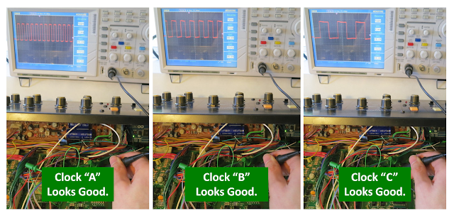
Listening for MIDI Aftertouch:  User, of course, is interacting with the keyboard via the keybed.  The keybed is connected to the keyscanner (both from Keyparts UK), which looks for which notes are pressed on the keybed.  The keyscanner outputs the notes via a MIDI stream, which is received by an Arduino Mega.  The MIDI stream includes the "note on" and the "note off" messages, as one would expect.  The keyscanner, though, also reads the aftertouch pressure sensor built into the keybed.  Therefore, the MIDI stream also contains the aftertouch commands.  So, after getting the keybed and keyscanner and Arduino hooked together, I used the Arduino to listen to the MIDI stream to ensure that the aftertouch messages were present.  They weren't.  After exchanging a few emails with the good folks at Keyparts, they sent me a new software build for the keyscanner (uploaded to the keyscanner using a very nice and very simple method via USB), which solved the problem.

Aftertouch for Vibrato:  With the aftertouch messages successfully reaching the Arduino, now the question is what to do with the messages.  In modern synths, the aftertouch can be mapped to a range of functions.  For me, I want to start simple -- I just want the aftertouch to create vibrato, much like what the mod wheel currently does.  The key is that I somehow need to command a smoothly-changing pitch from the Polysix.  I could implement this in a whole bunch of ways (and I even tried a couple).  Instead of going through the whole list that I came up with, I'm just going to talk about what ended up being successful.

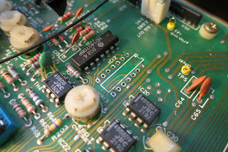
Polysix Pitch CV: First, let's talk about how the stock Polysix creates each note's pitch.  In the polysix, the sound that you hear starts with the VCOs (one for each voice).  The VCO is told what pitch to create via an analog voltage signal that is between 0 to +5V.  This is the "Pitch CV".  In a stock Polysix, the 8049 key assigner has 8 output pins, which are connected to an R-2R ladder circuit (a type of digital-to-analog converter) to create the Pitch CV (see schamtic below).  For each note being played by the Polysix, the 8 output pins of the 8049 are set in a particular combination of high (5V) or low (0V) states so that the correct CV value is created for the pitch that you want.  While it is a very nice system, it can only generate pitches that are precisely on the note you want -- it cannot create any pitches that are in-between notes.  As a result, I cannot exploit this circuitry to create the smoothly-varying pitches that I want for my aftertouch.

R-2R Ladder Used by the Polysix to Make Each Note's Pitch Control Voltage (CV)
DAC for Adjusting Pitch:  My solution is to use my own digital-to-analog converter (DAC) to create as smoothly-varying as a Pitch CV as I can. Granted, any DAC can only produce discrete voltages, but if the DAC has sufficient resolution (enough bits) then your ear will be tricked into hearing smoothly-varying pitch.  For expediency, I chose to use this product from Adafruit, which is an MCP4725 12-bit DAC mounted on a nice break-out board.  It's a fine device, but the best part is that Adafruit provides an easy-to-use software library for use with the Arduino.  It took zero debugging to get this to work.

DAC to Generate Pitch CV:  Ideally, I would have been able to use the DAC alone to be my sole device for create the Pitch CV in the Polysix.  In theory, it should have made the R-2R ladder unnecessary.  Unfortunately, when I actually tried to use the DAC this way, the pitches didn't sound right and weren't stable as I'd like.  So, either 12-bits isn't enough resolution for the full 10 octave span, or my use of it wasn't quite right.  Regardless, I abandoned the use of the DAC as sole generator of the Pitch CV and went to a hybrid approach.

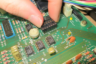
Using both the DAC and the R-2R Ladder:  In my hybrid approach, I return to using the R-2R ladder for the main part of the Pitch CV and use the DAC to provide a tweak to the Pitch CV to bend the pitch one way or the other.  To implement this hybrid approach, I needed to find a summing junction in the Polysix circuit that could be used to mix the DAC's CV with the R-2R's CV.  After trying a bunch of spots (including where the bend wheel injects its signal), I settled on injecting the DAC CV right after the R-2R ladder, at the junction of R33 and R34 (see schematic above).

Connect via 10K Resistor:  An important detail is that the 0-5V DAC signal must connected to this location via its own 10K resistor.   This makes the electrical summing at this junction scale correctly.  The reason that you need a 10K is that, for simplicity, I'd like our 0-5V DAC output to have the same pitch scaling as the 0-5V output of the R-2R ladder.  Since the R-2R ladder connects to this summing junction via 10K, then we should connect via 10K, too.  A second reason for the 10K is that the R-2R ladder uses +5V to represent the lowest note and 0V to represent the highest note.  So, we can call +5V to be the reference voltage with the higher pitches going down from there.  This is fine except that the VCOs can't work with that signal.  They need something more like 0V with higher pitch going up from there.  So, the designers included this summing junction using the -15V to strip off the +5V reference (see how the ratio of 10K to 30K is important!) and, by entering at the "-" input, the sign of the CV gets flipped.  It just so happens that this summing junction is a great place for us to inject our DAC signal as well...as long as we connect via 10K and as long as we make our DAC output with a 5V reference where increasing pitch requires the DAC to put out a lower voltage value.  The 10K resistor is easy, and the rest we do in software on the Arduino.

Real-World Implementation of Hybrid Pitch Control Via the 8049 Pins Plus DAC
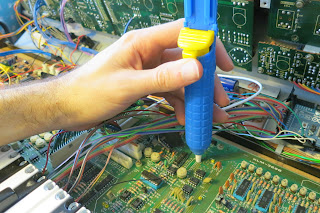
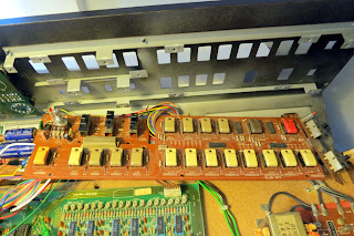
Wiring it All Together:  The picture above shows the messy real-world wiring for all of these bits and pieces.  It shows the rainbow-colored ribbon of wires going from the Arduino to the 8049 socket.  It also shows the DAC signal getting injected at R33/R34 via the black clip-lead.  Sure, it's ugly, but it works!  Well, I should say that, after a whole bunch of debugging of my software whatnot, it works!  I can receive MIDI messages from the keyscanner, interpret them in the Arduino, command the main part of the pitch via the 8049 socket, and command pitch adjustments (such as vibrato) via the DAC.  Nice!

Next Steps:  As shown in the very first picture at the top of this post, my system may function, but it is barely holding itself together.  Also, you'll notice that I've not yet included any demos...that's because there is still a big distance between being able to generate arbitrary pitches (including those critical in-between pitches) and getting a useful aftertouch-driven vibrato.  So, in my next posts, I'll talk about implementing the aftertouch vibrato (with portamento as a bonus!) and about my approach for cleaning up all that wiring so that the installation is a bit more permanent.  Stay tuned!

Update: Here's a demo once the synth was buttoned-up for the first time

Polysix - Aftertouch and Portamento Demo

$
0
0
This last week has been an exciting time for my pursuit of adding aftertouch to my Korg Polysix.  As you know by now, I *really* want aftertouch vibrato on my Polysix...so a while back, I ordered a bunch of parts and dived in. I've been posting about my progress.  In my last post, I described the electronics elements that I used to implement the arbitrary pitch bending that would allow for my aftertouch-driven vibrato.  As a bonus, having arbitrary pitch control also enabled me to add portamento to my Polysix, which is another effect that I absolutely love.  So, without further ado, now that I've put her back together, here's my first demo of what she can do...


How did I make this happen?  Well, the block diagram below shows the elements.  I bought an aftertouch-enabled Fatar keybed from Keyparts UK.  I bought their custom keyscanner, too, which scans the keybed and generates MIDI messages.  I then use an Arduino Mega to parse the MIDI messages and to drive the Polysix's electronics.  It interfaces with the Polysix by replacing the Intel 8049 microprocessor that is at the heart of the Polysix's "Key Assigner" circuit.  This this digital interface, I can control what note they Polysix is sounding.  To get the arbitrary pitch bending for the aftertouch vibrato and for the portamento, I generate an analog pitch control voltage (CV) using a digital-to-analog converter (DAC) from Adafruit.  I inject that signal at a pitch CV summing node that it already built into the Polysix.  After writing a bunch of code to run on the Arduino and after debugging these hardware elements, she works pretty well!

How I'm Implementing Aftertouch and Portamento
For a user interface, I'll eventually need to add some switches and knobs to the front panel of the Polysix.  For the moment, though, I've chosen to re-purpose the knob and switches that are supposed to be used to control the arpeggiator.  Since these particular elements are scanned by the Polysix's Key Assigner, and since I just replaced the Key Assigner with my Arduino, I now have total control over these particular user interface elements...so, I can make them do whatever I want.  For the moment, I'm going to use them for my aftertouch and portamento.

As you can see in the image below, I chose to make the arpeggiator "Speed" knob control my software LFO, which is driving my aftertouch vibrato.  The blinking of the LED still works to show the speed of my aftertouch vibrato!  I then use the arpeggiator "Range" switch to set the sensitivity of the aftertouch response.  Portamento is activated or deactivated using the "Latch" switch, while the amount of portamento is set using the "Arpeggiator Mode" switch.  Now I'm not saying that this is an intuitive user interface, but it sure is nice being able to use these elements to control my new features without having to cut into my Polysix panel.

Re-purposing the Arpeggiator Controls for Use with my Aftertouch Vibrato and my Portamento
So, I'm pretty excited about how she's working.  There are certainly more tweaks and adjustments to make, but the basics are all in place.  In fact, now that it's working, I don't seem to spend any time tweaking the electronics anymore...I just spend all my time playing.  I guess that's kinda the point, though.  :)

More updates later...when I get tired of playing!

Mono/Poly - Treble Boosting "Sizzle" Mod

$
0
0
After my recent successes with my mods to my Korg Polysix, I finally took some time to play my Mono/Poly again.  While I had a great time playing it again (such a big smile on my face!), the experience also reminded me how I wish that she had a bit more "sizzle".  Previously, I compared my Mono/Poly to my Polysix and confirmed that my Mono/Poly does indeed have less high frequency content than my Polysix.  So, my mission was clear...can I recover the sizzle in my Mono/Poly?  Well, after over-thinking this problem for way too long, I finally found a super-easy way of doing it.

My "Sizzle" Mod -- One Resistor and One Cap

The figure below was the key finding from by Mono/Poly vs Polysix comparison.  It clearly shows that the Mono/Poly is clearly missing some of the highest "sizzle" frequencies compared to the Polysix.  To put some numbers to this graph, the Mono/Poly is lower by 3dB at 4 kHz and it's lower by 10 dB at 10 kHz.  Now I have a quantitative target...boost the treble with a 3dB point at 4 kHz.  Let's go!

Measurements Comparing the Frequency Content Sawtooth Wave on My Polysix vs My Mono/Poly

Previously, I tried adjusting the Mono/Poly's VCF and achieved a slight improvement in the Mono/Poly's highest frequencies, but not enough.  I then dived into the internal signals isolated the high-frequency loss to somewhere in the VCF or VCA, but not in the VCOs and not in any of the circuitry that follows the VCA.  Having partly isolated its location, I assumed that I'd begin the detailed process of trying to find the broken component that might be causing the high-frequency roll-off.  While that's a noble goal, it then occurred to me that I could just take the easy way out and artificially boost the high frequencies in order to flatten out the synth's overall response.  That would be easy.

The easiest way would be to turn up the "Treble" knob on my keyboard amp.  That worked great until I got my Polysix and was running it through the same amp.  Cranking the Treble knob on the amp makes the Polysix way too hissy.  As a result, I now something that'll boost the treble on just the Mono/Poly.  Sure, I could add an EQ pedal, but that's more clutter.  It would be best if I could just add a bit of circuitry to the Mono/Poly and be done with it.

So, looked around the Mono/Poly's schematic and found a really nice-looking target for adding a little high-frequency emphasis.  Specifically, just before the VCF, there's a simple voltage divider that provides the massive amount of attenuation (50 dB!) necessary to get the signal level down to tiny level necessary for the input to the SSM 2044 filter IC.  As shown below, simply adding a resistor and a cap together around the 47K resistor in that voltage divider should result in a nice little treble boost.

Circuit Modification to the KLM-355 Board to Boost the Sizzle of my Mono/Poly
To get the specific values for theadd  resistor and cap, I used a circuit simulator (5Spice Analysis) to predict the effect of different component values.  As I said earlier, I was targeting a boost of 3 dB at 4kHz.  After a bunch of trial and error, I settled on the 5kOhm resistor and a cap that was in the neighborhood of 1nF.  The graph below is the output from 5Spice, which says that a 750 pF would be an even better choice because it yields +3.3 dB at 4kHz.  Unfortunately, I didn't have a 750 pF...I only had a 1000 pF (aka 1nF aka 0.001uF) on hand, so that's what I used.  Given the wide tolerances band on real-world caps (10-20%?), this analysis is all approximate anyway.
Expected Response of the Sizzle Mod Using Either a 1000pF or a 750pF Capacitor

After soldering in the resistor and cap (see picture at the top of this post...ugly!), I fired up the synth and measured the actual frequency response resulting from the modification.  The figure below shows that this mod did indeed boost the high frequencies quite nicely!

Measured Response of the "Sizzle" Mod to the Mono/Poly Relative to the Stock Mono/Poly

Now, to loop back around to the beginning, did I achieve my goal of giving the Mono/Poly a "sizzle" that is similar to my Polysix?  Well, if you care to believe in graphs (I do, obviously), the graph below compares the Mono/Poly's new response to my Polysix.  Check out those high frequencies...they're lined up stunningly well.  Mission accomplished!

Measured Response of the Modified Mono/Poly to my Polysix.  Mission Accomplished!
At this point, I'd love to present to you a sound sample comparing the modified to the unmodified Mono/Poly.  Unfortunately, I don't yet have a SoundCloud or anything for sharing audio.  So, while I could share it via YouTube, we all know that their audio compression can really mess with subtle and fine details of synth recordings.  So, sadly, I've got no sharing of sound right now.  Sorry!

Given how simple this mod is, though, maybe you should just give it a try yourself!  Smell the solder!

Update: I was guilted into posting some sound samples.  Check it out!

Mono/Poly - Audio Comparison of the Sizzle Mod

$
0
0
In this post, I showed how I modified my Korg Mono/Poly to boost the very highest frequencies to add a little more "sizzle" to its sound.  Because I'm lazy, I tried to get away without posting any sound clips of my modifications.  Well, I knew that I wouldn't really be able to get away with that kind of laziness.  I did have a couple of people ask me for some audio.  I've never posted a sound comparison before, so I'm hoping that this works.  Here's a comparison via YouTube....


Are you able to hear the difference due to the modification?  This was recorded directly out from the Mono/Poly into my M-Audio recording device.  VCO1 only, sawtooth waveform, filter wide open, no resonance.  To my ears, both the stock and the modified versions have lots of good "buzz", but the modified version has (to me) a little extra brain-tingling sizzle to it.  Hopefully, the YouTube audio compression still allows that extra little tingly sizzle to come through. (Note: when I play this video on YouTube, a weird hashy noise comes in around 0:45...that's YouTube, not my synth.)

Now, we should talk about the effect of subtle changes in sound.  In the demo above, maybe you'll hear the increased sizzle and buzz.  Or maybe you won't.  Or, maybe you'll say that the original version sounds better because it sounds more balanced, whereas the modified version has too much sizzle.  That's a fine opinion.  An important part of this equation is what sound reproduction equipment I use.  Recording straight from the keyboard into the computer (or M-Audio recorder, in this case) is not how I normally play, so the recordings in the video above are not representative of my everyday experience of how I hear my keyboard.

When I play, I play live through a keyboard amplifier with a big speaker (Roland KC-550).  Sure, there are higher-fidelity sound systems out there, but I just like that live feel where the bass from a big speaker really rumbles your guts.  The KC-550 has that.  Unfortunately, through this keyboard amp, the sizzle that you hear  in video for the stock Mono/Poly is often not apparent...the sizzle gets lost in the amp, or in the room, or in the off-axis orientation of my head relative to the amp.  With this modification, though, the extra sizzle makes it to my ears...and it makes me smile.  So, for me, the subtle 3-6 dB of added high frequencies makes a small but pleasurable difference.

Maybe six months from now, though, I'll be complaining about how I hate the sound.  I'll say that the extra high-treble is too fatiguing.  That would be so me.  I am a human being after all.  Very fickle.  :)

Thanks for checking it out!

Polysix - Re-Using the Arp Clock for the Aftertouch LFO

$
0
0
In a previous post, I demonstrated aftertouch in my Korg Polysix.  The aftertouch is used add vibrato -- an oscillating modulation of the pitch of the current note -- which is very similar to the effect of the mod wheel that is already built-in to the Polysix.  In fact, I originally planned on having the aftertouch utilize the same modulation generator (LFO) as used by the mod wheel.  But then I thought that it might be better to have the vibrato clocked by its own LFO thereby leaving the Polysix's built-in modulation generator free to do other effects like filter sweeps or tremolo.  Doing a vibrato-dedicated LFO in software in the Arduino is trivial, but how do I control its speed?  Is there a control on the front of the Polysix that I can re-purpose for controlling the vibrato LFO's speed?  Well, there is.  I chose to re-purposed the Arpeggiator's "Speed" knob.  Here's the story of how I did it.  (Note that I go into some gory details here, so you might just want to browse the pictures below and then go watch some funny cat videos.  I recommend this one).


The key limitation in this hack is that I do not (yet) want to add any more knobs or switches to my Polysix.  I would like to re-purpose one of the built-in knobs or switches.  This is made more challenging in that, because I have so far only replaced the Key Assigner microprocessor, I only have access to the knobs and switches that are serviced by the Key Assigner.  Most of the knobs and switches are actually serviced by the main processor in the Polysix, not the Key Assigner.  The only controls that serviced by the Key Assigner are (as shown in the picture below) the Arpeggiator controls and the Key Assign Mode button.  You know, that Arpeggiator "Speed" knob looks like it could be pretty useful...


One convenient property of the Arpeggiator controls is that they serve no purpose when the Arpeggiator is off.  Conversely, when the Arpeggiator is on, one is not likely to care about applying aftertouch vibrato.  So, we have a nice opportunity here to use the Arpeggiator controls for the Arpeggiator when in Arp mode, and an opportunity to re-use the Arpeggiator controls for another purpose when in normal mode.  Sounds good!

In the Arpeggiator controls, we see that we have a nice knob named "Speed".  It even has a blinky LED to indicate its current speed.   This seems like a perfect control for me to use to control my aftertouch vibrato.  How do we go about doing it?  Well, first we need to learn about what that knob is attached to, which means that we need to learn about the Polysix's Arpeggiator clock...

The Arp's "Speed" knob is wired into the circuit shown in the schematic below.  It is a circuit for generating clock pulses.  These pulses are used to drive the Arpeggiator when the synth is in Arpeggiator mode.  The "Speed" knob is wired into this circuit such that it changes the rate of these pulses so that the Arpeggiator goes faster or slower as desired.  It looks like the best way for me to re-use the Arp's "Speed" knob is to simply listen to the "ACKI" line and respond to changes in the rate of the pulses.


Looking at other parts of the schematic (KLM-366), the ACKI line is brought back to the Key Assigner's 8049 microprocessor.  Since I just replaced this microprocessor with my Arduino, it means that I have easy access to this signal.  I just need to figure out the best way to the Arduino to respond to this intermittent short pulses.  Using one of the Arduino's interrupt pins is clearly the best solution. If you're not familiar with interrupt pins, here's the idea:

Some of the Arduino's pins are special -- they can be configured so that they are always being monitored for changes, even while the Arduino is doing its other work.  Whenever a change is detected on one of these pins, the Arduino interrupts what it was doing and executes a special piece of code that you write called an "interrupt service routine" (ISR).  In the ISR, I would write the logic to measuring the timing of received pulses so that, back in the main part of the code, the vibrato LFO can adjust its speed.  There are three steps to implementing this:  (1) connect the ACKI line  to a one of the interrupt-enabled pins on my Arduino, (2) write an ISR, and (3) "attach" the ISR to the interrupt pin.  Let's go!

Step 1, Connect ACKI to an Interrupt Pin: The Arduino's interrupt pins are discussed on this page.  I'm using an Arduino Mega and you'll see that there are six pins that are capable of being interrupt pins.  For no particular reason, I chose to go with Interrupt 4, which means that I should use pin 19.  So I brought a wire from the ACKI line in my Polysix (from the now-empty 8049 socket) out to pin 19 on my Arduino Mega.

Step 2, Write the ISR:.  The ISR is a software routine will be called whenever a pulse is received from the Arp clock via the ACKI line.  After thinking about how to handle the timing of the vibrato's software LFO, I've decided that the ISR only needs to measure the time that has passed between the previous Arp clock pulse and the newly-receive Arp clock pulse.  Once I know the time between pulses, I can adjust my software LFO in the Arduino so that it'll cycle at the same rate.  Below is my ISR code for measuring the time between pulses.  The Arduino executes it whenever a new pulse is detected on my interrupt pin.

typedef unsigned long micros_t;         //data type returned by micros();
volatile micros_t previous_ARP_micros = 0;     //don't forget "volatile"!
volatile micros_t ARP_period_micros = 1000000; //don't forget "volatile"!

void measureInterruptTiming(void)
{
  //get the current time
  micros_t current_ARP_micros = micros();  

  //compute how much time has passed since the last pulse

  ARP_period_micros = current_ARP_micros - previous_ARP_micros;

  //save the current time for use when the next pulse arrives

  previous_ARP_micros= current_ARP_micros;
}

Step 3, Attach the ISR to the Interrupt Pin:  With the ISR written, now I need to tell the Arduino to execute this code whenever it detects a change on my particular interrupt pin.  This is called "attaching" the interrupt.  Following the documentation in the Arduino link above, I add this command to my void setup() routine:

attachInterrupt(4, measureInterruptTiming, RISING);

And we're done!  The result of this process is that the user (me!) can turn the "Speed" knob on the front of my keyboard, which changes the rate of pulses from the Arp clock, which is noticed by the Arduino via Interrupt #4 (aka, Pin 19), which causes it to run my ISR routine, which writes the time between pulses to a global variable, which is then acted upon in the main part of the Arduino software (not in the ISR) to adjust the rate of the vibrato.  Stated more succinctly, turning the "Speed" knob will now change the speed of my aftertouch vibrato.  And I did it without needing to cut any new holes in my Polysix for new knobs or buttons.  Mission accomplished.  Thank you Arduino!  Thank you Polysix!  Thank you reader!

Polysix - Mounting the Arduino

$
0
0
While I was pretty excited to jump straight to the end of my story to show a working demo of my aftertouch and portamento, there was actually quite a lot of work that had to get done to get to that demo.  That's why I'm now going back and hitting some of the details, like my last post on how I re-purposed the Arp controls for controlling the aftertouch vibrato.  In this new post, I'm going to talk about how I went about physically mounting my Arduino -- the brain for the aftertouch and portamento -- into my Polysix.  So that you can see where I'm headed, below is the final picture of it mounted inside my Polysix.

My Arduino Mega (in Blue) Mounted Next to the Power Supply
Compared to my Mono/Poly, the Polysix has far less space inside for adding stuff, and the Arduino Mega is not a small board to try to squeeze in.  Luckily, there is a nice open space on the sheet metal control panel, on the vertical part right next to the power supply PCB (see pic below).  It seems just right for the shape of the Arduino Mega.  But how will I actually attach it?

Well, because the Arduino Mega already has some mounting holes in it, I could just use screws.  But, to prevent pressing the backside of the Arduino against the electrically-conductive sheet metal, I need some standoffs.  Since most standoffs are threaded on both ends, the plan is to drill some small holes in the Polysix's sheet metal, mount the standoffs via screws through those holes, and then to use more screws to attach the Arduino to the standoffs.  Even for me -- the mechanically dis-inclined -- this seems feasible.

That Empty Spot is Where I'll Put the Arduino.  One Standoff is Already Mounted.
The first step was for me to find some standoffs.  For no particular reason (other than that they were easy for me to get), I got some #4-40 threaded aluminum standoffs (see below).  Plastic ones would probably work fine, too.  I think that I got standoffs that are 1/2" long, but they might have been a little shorter.  I also got a bunch of really short #4-40 screws and a few washers.  My screws were regular silver/gray color, which means that you can easily see the screw heads on the outside of the synth.  If I did it again, I'd try to find black screws so that they'd blend in better.

Threaded Aluminum Standoffs For Mounting the Arduino to the Inside of the Polysix.
With the standoffs in-hand, I then proceeded to drill the holes in the Polysix's sheet metal enclosure.  Drilling into sheet metal is not something that I wasn't familiar with, so I asked around at my work place.  Apparently, my regular (ie, cheap) drill bits can cut into sheet metal just fine.  Cool!  The only trick is that the drill bits have a hard time getting started on sheet metal.  Until they can bite in, they tend to wander around the surface of the metal, which makes it hard to get the hole where you want it.  So, according to one of helpful co-workers, I should use a punch-thingy to put a small indentation in the surface of the metal, which allows the drill bit to bite more easily.  The punch that I borrowed is shown below.

Spring-Loaded Punch for Making it Easier to Drill into Metal
Once I decided where I wanted a hole (by holding the Arduino up to the metal panel and using a thin pencil stuck through the Arduino's mounting holes to mark the spot on the sheet metal), I grabbed hold of the Polysix's panel, pressed in the punch, and waited for it to "pop!".  When it finally popped, it really startled my wife in the next room.  It's not particularly loud, but it is a bit sharp sounding and totally unlike any other sound that I usually make when futzing with my instruments.  It's good to keep things interesting around here.

Pressing in the Spring-Loaded Punch.
I'd like to now show a picture of the tiny dimple that was made by the punch, but it's really too small for me to take a good picture.  So, you'll just have to imagine a very very small dimple in the surface of the sheet metal.  I couldn't really believe that it was big enough to help the drill bit seat, but it was.  It worked marvelously.

With the dimple to get me started, I used a small drill bit to get my initial hole through the sheel metal.  Since I have old bits that aren't very good, it took me a while to get through.  Once I was through, I stepped up to a bigger bit to enlarge the hole so that my #4 screws would pass through.  

To then mount the standoff, you use one screw (and washer) from the outside of the back of the synth, you pass it through the hole that you just made, and you screw into the female threads in the standoff.  After tightening, the standoff is nicely attached to the synth.  In the picture above, you can see that two standoffs are already in place.

Once all the standoffs are in place (I used three), you can place the Arduino over the standoffs and use more screws to attach the Arduino to the standoffs.  If you're really lucky, you located your standoffs correctly and they line up with the holes in the Arduino.  I was mostly lucky...two holes lined up well and one was a smidgen off.  It was close enough, though, that I could angle the screw a bit and get it to seat sorta good enough.  As usual for me, it's ugly but it works.

Below is another picture of the Arduino fully-mounted inside my Polysix.  Not bad!

The Arduino is Fully-Mounted Inside my Korg Polysix
Now that I'm looking at this picture with fresh eyes, I sure do see a lot of loose wires running round.  In particular, lots of wires are needed in order to connect the Adruino, which is replacing the Key Assigner 8049 microprocessor, to the socket that used to hold the 8049 microprocessor.  The 8049 was located just underneath the keybed, so that's why you see the rainbow of wires passing from the Arduino on the right to the underside of the keybed on the left.  I'd definitely like a better way of handling all this wiring.  As usual, there's always more "cleaning up" that could be done!

Thanks for reading!

Polysix - Aftertouch Curves

$
0
0
After the success of simply getting the aftertouch system working on my Korg Polysix, now comes the effort to tune the response of the system so that the *feel* of the aftertouch is just right.  The feel of the aftertouch has a bunch of components: the physical resistance of the keybed, the force needed to initiate the aftertouch, and the sensitivity of the aftertouch to increasing pressure.  This last bit is defined by the "response curve", and it's the creation of my own response curve that I'm focusing on today.

Gathering Aftertouch Data via my Arduino Mega (the Blue Board in the Back)
The first step in tuning the aftertouch response is to be clear how aftertouch works in my system.  My new Fatar keybed (bought from Keyparts UK) has the aftertouch pressure sensor built-in.  This analog sensor is a long force sensitive resistor whose resistance drops when pressure is applied.  The sensor strip is plugged into the keybed scanning electronics (also from Keyparts UK).  The electronics include some sort of circuit that senses the resistance of the strip and generates a MIDI aftertouch message as pressure is applied.  The MIDI message includes a data field who's value is increases with increasing pressure.  What this sensor looks like, or how they convert their measured value into a MIDI data value, I'm not sure...but it has a strong effect on how the aftertouch feels.  It is especially important for defining the force required for the onset of the aftertouch effect.  Currently, I have no control over this part of the aftertouch response.

Once the electronics generate a MIDI aftertouch message, it is conveyed to my Arduino Mega via the Arduino's built-in TX/RX serial connections.  When the Arduino receives an aftertouch command, it induces pitch changes (vibrato) in the Polysix.  The magnitude of the vibrato is proportional to data value in the aftertouch MIDI message.  So, more key pressure generates a MIDI message with a bigger data value, which causes my system to put more vibrato on the pitch.  Easy.  But to be musically useful, the amount of vibrato needs to be controllable via the amount of force that I put on the keybed (not just ON or OFF), which means that the scaling between key force and vibrato response needs to be just right.

So, to get that scaling "just right", we need to get quantitative.  I need to record the actual aftertouch values generated by my system as I press on the keys.  Since I've got the Arduino in the system, I'm able to easily echo the MIDI aftertouch messages through the Arduino to my PC for logging and analysis.  Below is a plot of the aftertouch data values logged by my PC for three key presses.


As you can see, the aftertouch values span 0-127, which the full range allowed in the 7-bit space afforded by aftertouch MIDI message.  The next thing to notice how steep the curves are at the beginning and end of the each key press.  Being very steep means that my vibrato comes on strongly and suddenly.  My goal is to smooth that out so that I can have better control over more subtle amounts of aftertouch-induced vibrato.

My approach is to take the in-coming aftertouch value and to re-map it to a new value using my own aftertouch response curve.  The new response curve will be shaped to reduce the slope of the onset of the aftertouch.  Since I don't have the ability to set the response curve inside the keyscanning electronics (yet), I will have to implement the new response curve in the Arduino.  Fine.  But what response curve should I use?  I don't know.  We'll have to try some out.

Below is one of the first candidate curves that I tried.  It is simply two linear segments stitched together.  For small aftertouch values (like the onset), the slope is reduced so that the onset is more gentle.  This sounds like what I want.  The plot on the right shows the data from one of the key presses from the graph above.  The blue curve is the raw data.  The green curve is the re-mapped data.  Note that, yes, the steep onset is reduced, but I don't like that flat plateau that follows the onset.  That plateau will feel like a dead spot where nothing happens.  That isn't good.  Pressing harder should give a stronger response.  This is a Fail.


My next attempt at a new response curve was just a shot in the dark.  I tried an exponentially shaped curve because I knew that it would have a gentle slope at the beginning of the response and that it would smoothly transition up to its steeper portion (see the left-hand plot below).  Sounds good, right?  Unfortunately, as you can see in the right-hand plot, it's onset is far too gentle and its output stays low for far too long.  Then, finally, towards the climax of the keypress event (when the force is highest), the response suddenly leaps relatively from a low value up to the maximum allowed value.  Bad.  Again, Fail.


I then tried a whole bunch of other curves.  Lots and lots.  You can see many of them plotted together in the figure below.  Some of them looked decent enough on paper to be worth trying on the Arduino.  So, I coded them up as a simple look-up table and gave them a test drive.


After trying a bunch of curves, and after iterating the details of the most promising candidate, I finally converged to the curve below -- a curve made up of 4 linear segments.  As you can see in the right-hand plot, the new onset and release seen in the green curve is very smooth.  It gives me the best control (that I could find through this guess-try-and-tweak method) over both subtle and strong amounts of vibrato.  It feels pretty darned good!


My remaining criticism with the response of my aftertouch is that it takes too much force to get the aftertouch started.  Sadly, I have no control over when the aftertouch starts -- the start of the aftertouch is entirely set by when the keyscanning electronics decide to start generating MIDI aftertouch messages.  Don't get me wrong, I think that the folks over at Keyparts UK set a very good general-purpose aftertouch threshold into their keyscanning electronics.  I just think that *I* like my aftertouch to start with far less force than most other folks.  I like it to start with a mere feather of a force...an amount that would drive other folks crazy.

To address this "problem", I'm thinking that there's probably a configuration setting in the keyscanning electronics that'll let me adjust the aftertouch threshold.  The electronics are amazingly configurable and under continued development.  I think that it's time for me to dive in and figure it out.  Fun!

Portamento Voice Spreading from the Mono/Poly

$
0
0
Getting aftertouch and portamento hacked into my Korg Polysix felt like a pretty good achievement.  Now comes the part where I tune their response so that they feel just right.  Last time, I spent some time adjusting the feel of the aftertouch.  This time, I'm tuning the feel of the portamento.  Specifically, I'm stealing some ideas from my Korg Mono/Poly to make the portamento more exciting and more engaging.


When I first implemented portamento, I coded it up as quickly as I could, which meant that I kept it as simple as possible.  I wrote a nice pitch-slurring portamento function for my Arduino key assigner, the core of which boils down to equation below.

change_in_note = (desired_note - current_note) / time_constant;

In my Polysix, the Arduino's job is to continually looping over each voice to update its pitch (and whether it is "on" or "off").  Based on the last MIDI note received from the keyboard, the Arduino knows what the desired note is for each voice.  Because of the portamento, though, we need to transition from the current note up to the desired note.  As the Arduino loops over each voice (returning to a given voice every 6 ms or so), it updates the pitch of the voice using the equation above.  Since all six voices use the exact some portamento equation, they all slide in the exact same way.  Easy enough.

The result of this portamento approach is shown in  spectrogram below (time on the horizontal axis, pitch on the vertical axis).  This spectrogram was created based on an actual recording from my Polysix with all six voices active and set to a "C".  I then step from C1 up to C4.  As you can see, the pitch transition is nice and smooth from low to high (nice exponential!).  It sounds nice and smooth, too.  The problem, though, is that it's too "nice" and too "smooth"...it's a bit boring.

Output from Polysix, Initial Portamento Algorithm.  6 Voices.  Smooth Shift from C1 to C4.  
On my Korg Mono/Poly, the portamento sounds much more exciting and engaging.  Why?  I don't know why.  To figure out why, I made a recording of the Mono/Poly and made a spectrogram.

Output from Mono/Poly with Portamento.  4 Voices.  Smooth Shift from C1 to C4.
How is it different from the spectrogram of my portamento on the Polysix?  Well, a careful eye will see that each spectral line gets fatter during the transition from low to high.  What's going on there?  What's making it fatter?  To figure that out, let's zoom out and then plot what's happening to the higher frequencies during this portamento slide.

Zoom to Higher Frequencies Where the Mono/Poly's Voices Are Spread by the Portamento.
Up at these higher frequencies, the harmonics are finally spread out enough for the spectrogram to have enough resolution to see what's happening.  And what do we see?  We see that the four individual voices of the Mono/Poly are getting spread out during the slide up to the new note.  They aren't playing one uniform pitch during the slide -- they're playing four different pitches during the slide.  Eventually, the four voices settle onto the same pitch, but during the transition they're all different.  That would certainly make for a more interesting sound!

Looking at the schematic for the Mono/Poly (KLM-354), you can actually see that the designers purposely used different capacitor values in the portamento circuit for each voice.  This means that each voice has a different time constant (ie, speed) for its portamento pitch changes.  That's cool!  Different time constants for each voice?  I could do that in my portamento equation!

Looking at the spectrograms for the Mono/Poly, I see that the slowest pitch change takes about 30-50% longer than the fastest pitch change.  So, that means that the time constants differ by 30-50%.  In my portamento equation, that means that "change_in_note" needs to be scaled different for each voice so that they don't all move together.  Below is one way of making the note change be voice dependent with fixed-point math.  This will result in the slowest voice taking 42% longer to get to its steady value compared to the fastest voice.

int voice_time_constant = time_constant;
int spread[] = {12 13 14 15 16 17}; //spread the voices!
voice_time_constant = (voice_time_constant * spread[voice_index]) / 12;
change_in_note = (desired_note - current_note) / voice_time_constant


When I implement these equations in my Arduino portamento routine, here's how the Polysix responded.  Looks pretty good!

Revised Portamento in my Polysix.  6 Voices.  Notice the Spreading of the Voices!
So, how does it sound?  You can hear it for yourself in the YouTube movie at the top of this post.  I think that it sounds far more exciting and engaging than the original portamento algorithm.  I really like the spreading of the voices.  To my ears, it sounds fantastic.  Does anyone know if other old analog synths purposely spread the voices in this way?  Or, was the Mono/Poly unique?


Polysix - Adding "Detune"

$
0
0
After adding the hardware and software to implement aftertouch vibrato and portamento, I realized that I could command the Polysix to do all sorts of arbitrary pitch-manipulation effects.  With just a little bit of additional software, I could do pitch bends, pitch wobbles, pitch slides (hence the portamento), pitch transposition, or...wait for it...pitch detuning.  I love the detuned unison sound on my Mono/Poly and now I can get it on my Polysix!


It should be noted that the Polysix already has a little detuning purposely built into its Unison mode.  The circuit below is on the KLM-366 PCB and is only active in Unison mode.  Via voltage dividers (R120-R122 per voice combined with R116 for all voices), this circuit generates a small voltage that is used to shift the pitch of each voice to be a little sharp or a little flat.

Polysix's Built-in Detuning Circuit for the Unison Mode
By looking at this piece of the schematic, it looks like this circuit leaves Voices 1 and 6 unchanged.  It appears to shift Voices 2-4 up or down by between 16 and 33 mV.  The schematic says that the pitch scale is 5V/oct at this point, so the per-voice pitch detuning is about 4-8 cents (4-8% of one half step).  While that's enough to give a nice little swirl to the Unison mode, it doesn't give that meaty, fat detuned sound that has become popular in some electronic dance music styles.  I intend to change that.

In terms of approach, one could simply modify the existing circuit.  By replacing R116 with a bigger resistor (say 400-600 ohms), the detuning would get much more intense.  It would still be a fixed amount of detuning, but it would be a very easy modification.  The down side is that it is not adjustable (unless you wired in a potentiometer) and that it only applies to Unison mode -- it is not usable by Chord Memory mode.

Since I already have my Polysix modified with an Arduino and a digital-to-analog converter (DAC), I can do arbitrary pitch shifts and pitch bends on a per voice basis in any of the Polysix's modes of operation.  That's a lot of pitch-mangling power.  So, I wrote a little bit of software that, when I commanded the Arduino to effect "Detuned Mode", it would command a slight pitch shift to each of the Polysix's voices.  How much pitch shift per voice?

Well, following from the Polysix's built-in detune, I left two of the voices at normal pitch and bent the other voices in pairs (one up, one down) to different degrees.  The overall scale factor for the detuning I left as a variable that I could adjust on-the-fly so that I could control how much detuning I wanted.

Spectrogram of Output of Polysix While Adjusting the Amount of Detuning
For my user interface, I've temporarily mapped "Detune Activate" to my Polysix's arpeggiator button.  Pressing the arp button activates or deactivates the detuning.  Then, I can control the amount of detuning by holding down the arpeggiator button and turning the arpeggiator's "speed" knob.  My Arduino sees the button being held and sees the knob being turned and interprets that as a command to adjust the detuning.  It works great!  The spectrogram above really shows how the voices spread apart as the amount of detuning is increased.

How does it sound?  Well, the video is a demo of the audio coming out of my modified Polysix.  At the very beginning, you hear me load up the six voices playing the same note.  I lock in the six voices using the Chord Memory button. You hear that the voices are in pretty good unison.  Then you hear me kick in the detuning.  I like it a lot.  Yes.  A lot.

Thanks for reading!

More Info: Choosing my Polysix's default detuning amount based on the Mono/Poly

Mono/Poly - Amount of Detuning

$
0
0
In the process of adding detuning to my Korg Polysix, I spent a bit of time looking in detail at the detuning on my Korg Mono/Poly.  I've always liked the sound of the Mono/Poly's 4-voice unison with the Detune knob cranked up a bit.  So, as I was setting up the detuning functions on my Polysix, I looked at the detuning on my Mono/Poly to act as a guide.  This is the story about what I found...

Mono/Poly VCO2 with Maximum Detuning -- Flat by 30-35 cents.

I started my investigation experimentally.  I put the Mono/Poly in Unison mode and locked in a "C" using the Hold button.  Using each voice's Level knob, I listened to the pitch of each voice by itself.  By turning the Detune knob, I could hear what the detuning did to each voice.  To my surprise, the Detune knob had no effect on VCO1 or VCO3 -- it only affected VCO2 and VCO4.  At this point, if you look at the block diagram in the Mono/Poly service manual (see the figure below), it clearly shows that Detuning only affects voice 2 and 4.  I had never noticed this before.  I found it to be an interesting design choice by the Korg engineers.

Block Diagram from Mono/Poly Service Manual.  Detuning is only on VCO2 and VCO4.

My next goal was to quantify the amount of detuning that is generated by the Mono/Poly.  Looking at the schematic (see the bottom of page for the KLM-357 PCB), the circuitry involved with distributing and scaling the detuning control signal is too complicated for me to figure out quickly.  So, instead, I returned to my experimental approach and just measured the out-of-tuneness generated by the detune knob.

Mono/Poly VCO4 with Maximum Detuning -- Sharp by 20-25 cents.

I found that with the Detune knob set to maximum, VCO2 was driven flat by 30-35 cents and that VCO4 was driven sharp by 20-25 cents.  While it's somewhat interesting that the pitch deviations are slightly different for the two VCOs, I'm thinking that the difference is not purposeful and is actually just due to imprecision in the circuit components.  What I think is more interesting is that they chose to do a balanced de-tuning with one voice driven sharp and another voice driven flat.  Taken as an ensemble, therefore, the overall pitch of the four oscillator cluster is basically unchanged for any setting of the Detune knob.

Compare this approach to your more typical 2-oscillator-per-voice monosynth or polysynth.  Whether it's an old Minimoog or a Prophet-5, it is my impression that detuning is usually effected by changing the pitch of just the 2nd oscillator while leaving the 1st oscillator at the original pitch.  If this is true, it means that the ensemble of the two voices together is always a bit sharp or a bit flat.  Since these other synths are wonderful instruments and people love them, this unbalanced detuning must be an acceptable approach...but I've always felt that the detuned sound of the Mono/Poly just felt more "right".  So, in adding detuning to the Polysix, I chose to use the balanced detuning approach.

Due to the limited number of knobs and switches on the Polysix that are seen by my replacement Key Assigner (ie, my Arduino), I don't have a knob that I can dedicate to the Detune function.  Instead, I'm going to use a push button to turn the Detuning "on" with some default detuning factor.  I did include a method to adjust the amount of detuning (a complicated press-the-button-while-turning-the-knob combination), but I'd like to get the default detuning correct so that adjustments are usually unnecessary.


How much detuning to I want to be my defualt?  On the Mono/Poly, when i'm really getting the party started, I like to set the Detune knob to 5-6, which is 50%-60% of the total amount of detuning available on the Mono/Poly.  Given that full detuning is (take the average of VCO2 and VCO4) is about 27 cents, my target detuning amount for the Polysix should be about 14-16 cents.  The Polysix has six voices to detune, so I chose to detune two voices by 14-16 cents (one sharp and one flat), two voices by 7-8 cents, and two voices were left unchanged.  I then coded these values into my detuning routines on my Arduino and, as you can see below, I got 15-20 cents...pretty darned close to my 14-16 cents target!

Detuning Amount on my Polysix...about 15-20 cents.  Just what I wanted!
Like you can see in my demo video, the detuning works well on the Polysix -- I find the sound very engaging.  My experience with the Mono/Poly was really helpful in tweaking the detuning so that it sounds right.  Thank you Mono/Poly!

Killing and Reviving my Polysix (Replacing a Dead IC)

$
0
0
So far, I've been pretty successfull with hacking aftertouch, portamento, and detuning into my Korg Polysix .  My next big goal is the addition of velocity sensitivity, which requires me to better understand the VCF control circuitry on KLM-366.  Well, in probing the clock signals for the VCF multiplexing, I killed my Polysix!  This is the story of how I brought her back to the land of the living.

Probing IC12 on KLM-366.  I think that I've found the problem.
How Did I Kill It?  This all started when I was probing around the part of the KLM-366 board that processes the VCF EG signal for each voice.  Specifically, I was exploring the time-division multiplexing of the VCF EG through IC24 and IC23 .  This multiplexing is all kept in sync via clock signals "A", "B", "C", and "INH" that are generated from IC11 and IC12 (schematic below).  In probing IC12, I accidentally shorted one of the pins on IC12 (likely pin 11), which apparently killed it.  As you can see in the pictures above, the "B" signal is clearly bad (it is supposed to be a square wave pulse).


How Do I Fix It?  Replacing IC12 seemed like the only reasonable answer.  The chip itself is really cheap (68 cents).  The hardest part in replacing the IC is disassembling the synth so that I can get good access to the circuit board.  I don't like taking it apart because it gives me too many opportunities to loose screws and to re-connect connectors in the wrong place and stupid stuff like that.  But, in this case, I think that it needs to be done.

Shopping List:  The only part that I really needed was a replacement 14024 chip.  Like usual, I got it from Digikey.  The specific part that I bought was MC14024BCPGOS-ND.  I chose this part because (I think) it is the only through-hole version of the 14024 that they sell.  At 68 cents, I bought 2, just in case I damaged one during my installation.  Also, following the advice from The Old Crow, I decided to install an IC socket at IC12 in order to ease any future replacement of this chip. There are tons of choices for sockets.  Never buy the cheapest ones.  I liked the look of A32869-ND.  Even though it was only 78 cents, it seemed to be one of the higher end models.  Cool.

Removing the Dead IC.  The replacement process starts by removing the dead chip.  Some helpful folks at my workplace suggested that removing an IC is best done by first snipping off each of its legs so that the body of the IC just falls free of the PCB.  Then, as long as you snipped the legs high enough away from the board, there's plenty of leg left to grab with your pliers so that you can apply a little heat and lift each leg out one-by-one.  Pretty easy.

Snip Each Leg of the IC
All Legs Are Snipped, The Body is Loose, and the Legs are Still in the PCB.
Removing Each Leg from the PCB.
Removing the Old Solder:  Even after removing the IC's legs, there was lots of old solder that is plugging the holes in the PCB.  In order to get the new IC socket into all those holes, it's usually best to remove that old solder.  There are a few ways that you can do this -- solder wick and a solder pump being the two most common.  Clearing plugged through-holes is a perfect task for a solder pump.  With a solder pump, you first apply your soldering iron to the hole until the solder melts.  Then, you quickly put the spring-loaded solder pump over the hole and, while the solder is still melted, you hit the release button.  BANG!  The pump pops open and (hopefully) sucks out the liquid solder.  Because I'm new to this, I usually had to try 3-4 times before I got the solder out.  As you can see below, the holes looked fairly clear when I was done.

Using a solder pump to suck out the solder from the holes.
The holes are now fairly clean and ready for the new IC (or socket).
Installing the IC Socket:  At this point, I was able to insert my new IC socket into the holes in the PCB (see below).  It fit pretty nicely.  Now I just needed to solder it in.  Unfortunately, one really needs access to the bottom of the PCB to do this, which means the synth needs to be partly disassembled.  So, I removed the keybed, I removed the rail holding down the PCBs, and I unscrewed all the screws holding down the PCB.  I then removed a few (but not all!) of the multi-pin connectors so that I could tip up the PCB and get access to the bottom (see pic below...the power drill is holding the PCB upright).   Once I was able to access the bottom of the PCB, I was soldered the legs of the IC socket to the PCB.  We're cooking right along now!  Smell the solder!

Inserting the IC Socket.  It fits!
Getting access to the bottom of the PCB.
Soldering the legs of the IC Socket.  Heat the site and THEN apply the solder.
Finishing Up:  Once the socket was soldered in, I layed the PCB back down and I inserted the replacement 14024 IC into the new socket (see pic below).  I then re-attached all the connectors that I had undone, I double checked that I re-connected everything correctly, and I turned on the power.  With the oscilloscope, I checked the "A", "B", and "C" clock signals being generated by the new 14024 (see pic below).  Everything seems to work!

The replacement 14024 IC is nestled into its new home on my KLM-366.
After Replacing IC12, the clock signals all look good.
Oh, The Joy:  With the circuit looking like it's working again, I re-attached the keybed, closed the lid, and fired her up.  Here's my little jam of joy...the playing is crappy, but it's so good to hear her voice again.


Polysix - Bending Over the Capacitors

$
0
0
Dear Readers, I'm sorry.  Back when I described how I prepared my new keybed for installation into my Korg Polysix, I made it sound fairly straight-forward with no real hiccups.  Sure, at the end, I mentioned something about how a couple of capacitors might have been a little too tall, but this was actually quite a large understatement.  It turns out that those "too tall" capacitors required that I boost up the keybed even further than shown originally, which then prevented the Polysix's control panel from closing.  It was ugly and frustrating and disheartening.  Here's a description of how I fixed the problem.

Here Are the Offending Capacitors That Interfere with the Keybed
As you can see in the picture above, there are two groups of offending capacitors.  Both sets of caps happen to be on KLM-366.  The first group are the six tall Mylar caps (C31-C36) that are part of the "hold" circuits between IC29 and IC25.  The second group of interfering caps include the tall Mylar cap C23 and the stout electrolytic cap C22, both of which are part of the pitch-correction feedback circuit.  At first, I thought that the solution might be to replace all the caps with smaller ones (such as ceramics).  But after a brief exchange with the Polysix Yahoo Group, I considered alternate approaches.  With fresh eyes, it seemed like the best plan was to simply bend over the capacitors so that they weren't as tall.  Easy!

Could I Just Tip the Capacitors to the Side to Make Them Less Tall?
Unfortunately, the caps were mounted very close to the PCB and didn't have enough of their leads above the board to enable me to tip them over.  Since I just replaced an IC on this PCB, though, I have the synth all apart and, therefore, I have full access to the bottom side of KLM-366.  Looking closely, I saw that each cap had a little bit more of its legs sticking out below the PCB.  So, I got out my soldering iron, I applied some heat to the tips of the legs until the solder melted, and then I pushed until I couldn't see the tips of the legs anymore.  See the picture below.

Looking at the Underside of the PCB.  Making the Caps Taller By Pushing on the Tips of their Legs.
Once I did this, the first cap was now taller than it had been because of the extra bit of each leg that I pushed back above the PCB.  Now it was tall enough that I could tip it over with ease.

Bending Over Worked well for the First Cap.  Now for the rest...
After repeating the process for the remaining five capacitors, things are looking pretty good.  Now it's time for the other two caps.

The Six "Hold" Caps Are Done.  Now It's Time for C22 and C23.
The tall Mylar cap on the left side of the picture above was easy to address -- I simply did the same trick of re-heating the solder joint and pushing up the extra bit of each leg.  Then, I bent him over.  The electrolytic cap, though, was too stout (too fat) to push over.  Having a bunch of electrolytic caps on hand, I decided that it would be easier to just replace this guy with one that was skinnier and that had long enough legs to bend over.  So, I de-soldered the old one and soldered in the new one.  I bent it over and, as you can see below, everything is shorter than it was before.

All the Caps are Now Much Shorter Than Before.
With all of the steps complete, I put the keybed back into the synth.  Did it fit?  Well, the part of the keybed that was near the caps fit great.  That problem was solved.  But, with that part of the keybed sitting correctly, it now revealed that another part of the keybed was interfering with something within the case of the Polysix.  A little poking around showed that the long white bar of plastic that I added to my keybed wanted to sit right on top of the rail that holds the whole front side of the KLM-366 and KLM-367 boards.  That's an easy fix that I'll talk about later (just cut that darned plastic bar!).  For now, though, we can be content that this cap-bending job was the key.  It was the key to enabling the keybed to sit properly in the Polysix's case and for the lid to close properly and for the whole thing to be beautiful.  Ah...joy...

Polysix - Replacing a Push-Button

$
0
0

We all know that, given their age, most Korg Polysix's have problems.  Usually, the problems are related to the dreaded "leaking battery" problem.  My Polysix had that problem and I fixed it (I hope).  My Polysix, though, also had a problem with the push-buttons being very finicky.  I think that this is a common problem, too.  I've replaced many (but not all) of the switches when I first got the synth.  Recently, though, my "Arpeggio" button started acting up, so I decided to replace it.  For anyone who needs to replace any of their buttons, here's a picture tour of the process.  (By the way, the buttons on the Korg Mono/Poly are the same, so this applyies to Mono/Poly owners as well!)

I replaced the Arpeggio button and now it works great!
The general outline for replacing one of the push-buttons is:
  1. Open the synth
  2. De-solder the old button and the associated LED leads
  3. Un-fasten the button's PCB from the synth
  4. Remove the button cover
  5. Remove the button itself
  6. Solder in the new button
  7. Re-attach the button cover and solder the LED leads
  8. Re-attach the button's PCB to the synth
  9. Re-fasten the PCB and close the synth
So, here we go with pictures and description and tips:

(1) Open the Synth:  I don't have any pictures of this because it is pretty straight-forward.  Unscrew the four screws on the cover panel and unscrew the four (?) screws on the bottom of the synth that secure the bottom lip of the cover panel.  Once you've got the synth open, you've got to find the PCB holding your button.  Since I'm replacing the Arpeggio button, it was pretty easy for me...they labeled it!  Note that they spelled it "Arpeggo" (oops!), which amuses me.  But, since we're talking about labels on PCBs, why are the labels in English?  Wasn't this synth designed in Japan?  Why aren't the labels in Japanese?  I've never understood why there's so much English on circuit boards made throughout the world.  

Here's the back of the Arpeggio button.  De-solder all six solder points.
(2) De-Solder the Old Button and LED Leads:  To de-solder the button, you'll note that there are six solder points.  Four are for the legs of the push-button and two are for the LED that's built into the button cover.  You'll need to de-solder all six.  You can do this using solder wick and/or a solder pump.  I used the pump for the bulk of the work (see my earlier post for a bit more description) and I used the solder wick to wipe up (soak) up the little bit of solder that remained.

First, apply heat until the solder melts.
Use the solder pump to suck out the molten solder.
After a final touch-up with the solder wick, here's what it looked like. 
(3) Unscrew the PCB:  To get the button off the PCB, you'll need to detach the PCB from the synth so that you can get access to the top of the synth.  The PCB that holds the Arpeggio button has lots of screws.  You need to remove them all.  This particular PCB is also connected to two daughter PCBs.  You'll need to unscrew those as well.

There are lots of screws to remove on this PCB ad its daughter boards.
One of the daughter PCBs holds the potentiometer Arpeggiator Speed control.  To free the PCB from the synth, you need to remove the plastic knob...just work your finger tips under the lip of the knob and pull it off.  Then unscrew the nut that holds the potentiometer to the case.  Easy.

For this PCB, you also need to remove the knob and the nut on the potentiometer.
You'll notice that you've collected quite a few bits and pieces from your synth at this point.  You've got screws from the synth's case, you've got screws from the PCB(s), and you've got the knob and nut from the potentiometer.  Don't loose those bits!  I have a set of little bowls that I use anytime that I remove items from my synth.  If the bits go into the bowl, then I know where to find them when I go to re-assemble the synth.  Any bits that remain in the bowl when I'm  "done" are a reminder that I must have missed something.  The bowl is critical!

I keep all of my screws and knobs in a little bowl while I work.
And now the PCB is no longer secured.  This particular PCB requires a little twisting and sliding, but eventually it comes from from the panel.

The PCB is free!
(4) Remove the Button Cover:  These push-buttons are composed a two main parts: the button itself and a button cover [*see comment section at bottom].  The button itself is what we need to replace.  It lies under the button cover.  The button cover is the colored plastic piece that you actually touch with your finger.  The button cover also holds the red LED that lights up when you press the button.  The button cover is what we need to remove first.

The button cover is held on to the PCB once the legs of the LEDs are soldered to the board.  The button cover is also held on through friction with the button itself.  To free the button cover, I generally use my soldering iron on the bottom of the PCB to push the leds of the LED up into the board (the soldering iron also melts any residual solder that might be holding the LED legs).  At this point, I can generally wiggle or pry the button cover off the button.  Once you do one, you'll have more confidence when you do others.

The button cover has been removed from the button.  Notice the two legs of the LED sticking out of the button cover.
(5) Remove the Button:  The button itself is held to the PCB by its four legs.  The legs are both soldered in place and they have a certain bend in their shape that helps them grab the board.  You've already removed most of the solder, but there might be a little left in there.  So, I again take my soldering iron and, from the bottom of the board, try to push each leg back into the PCB.  I'm trying to push the button up off the board through pushing on its legs.  I also use my needle-nose pliers to try to pry under the button while I'm applying the heat.  Surely, there is a better way of doing this, but eventually I'm able to get the buttons off. 

Using a soldering iron and pliers, I eventually get the button off the PCB.
(6) Attach the New Button:  Before you solder the new button, you need to buy a new button.  Via a post by Anon on the Polysix Yahoo Group, I was pointed to some Omron 12mm x 12mm tactile switches that did the job.  From Mouser, I ordered some Omron B3F-4000 and some B3F-4005 -- the only difference between the two being the amount of force necessary to activate the switch.  Once installed in the synth, I couldn't really tell the difference between the two, so either is fine.  The B3F-4005 is shown in the picture below.

An Omrom B3F-4005 P
To mount the switch to the PCB, line of the legs of the button with the holes in the PCB.  At this point, I usually get out the soldering iron (again) and heat the hole from the underside so that I melt any solder that might still be in the hole.  I then push one of the button's legs part-way (or fully) into the hole.  I then repeat for the other legs.  Once all four legs are in the holes, I heat and solder from the bottom of the PCB like normal.

Lining up the legs of the button with the holes in the PCB.
Unfortunately, because I'm no expert at doing this, I damage the PCB when I push the legs through the hole. As can be seen in the picture below, I lifted one of the solder rings up off the PCB.  This is definitely the mark of an amateur.  Lucky for me, all four legs of the switch are soldered into the circuit, which means that there is redundancy...I can loose one of the connections (due to the lifted solder ring) and still have a good solid button.  Lucky!

I lifted up one of the solder rings.  Dang!
(7) Re-Attach the Button Cover:  Once the button is soldered in, we can now re-attach the button cover. First, I line up the button cover with the button, including the legs of the LED with the holes in the PCB.  I then push the legs of the LED through the PCB holes, usually with some heat from the soldering iron to melt any left-over solder that's in the hole.  Once the legs are through the hole, I make sure that the button cover is fully-seated around the button itself.  Then, on the bottom of the PCB, I solder the legs of the LED like usual.

Seating the Button Cover on the Button.
(8) Re-Fasten the PCB and Close the Synth:  The work with the button is now done.  To finish, simply, re-fasten the PCB to the inside of the synth (do you still have all the screws?) and close panel of the synth (do you still have those screws, too?).  Turn on the synth and enjoy your new button!

The Button Now Works Great!


Polysix -- Taking its Temperature

$
0
0
After my long string of modifications to my Korg Polysix, I've now got several additional electronic components drawing power from the Polysix's built-in power supply.  I've been worried that I might be taxing the power supply too much.  Feeding this fear is that, when I touch the back of the Polysix, it seems awfully hot.  Since I don't have an unmodified Polysix to compare to, all I can do is take some measurements and see if anyone out there on the Internet can confirm if my readings are normal, or if they're too hot.  Does my Polysix have a fever?

To measure its temperature, I'm using the thermocouple that came with my digital multimeter.  It's a hot day here in the Northeastern United States, so as you can see below, the ambient temperature is 86.4 F (30 C).


After playing my modified Polysix for about 30 minutes, the picture below shows that the back surface of the Polysix is reading almost 109 F (43 C).  It is quite warm to the touch.


Opening up the Polysix, I measured the temperature of the metal bar that is acting as a heat sink for four of the voltage regulators.  Poking around a bit, I find that the hottest spot is between the third and fourth regulator.  It is reading 138.4 F (59 C).  That's getting  pretty hot!  I also measured the temperature of plastic casing of each of the four regulators, and they were all lower than the temperature of the metal bar (which was a bit surprising).


While I had the synth opened up, I also measured the temperature of the transformer.  it was reading 123.5 F (51 C).  While that's really warm, it could certainly be worse.


So, my question for all of you is whether you think that 140 F (60 C) is too hot for the power supply.  Am I over-taxing the power supply?  What is the temperature shown by an unmodified Polysix?

To be truthful, I'm actually interested in drawing even more power from the built-in power supply.  My mind is currently dreaming of 6 Arduino Micros (or 6 Femtoduinos) to add a second oscillator to each voice*.  I'd like to use the built-in power supply to power these additional units.  If my existing modifications are already causing this much additional heating, I'm thinking that it would be unsafe for me to draw even more power.  Thoughts?

(* Yes, I could use a single microcontroller to create all six new voices, but I want to do the six voices as wavetable oscillators where the sample rate changes to effect the desired pitch.  Since the sample rate will be driven by an internal timer interrupt, and since I don't want the 6 different timers conflicting with each other, I think that I need 6 separate microcontrollers.  That's a lot of additional power draw.)

Update: Here I compare the temperature to my de-modified Polysix.

Polysix - Adding a Sustain Pedal

$
0
0
A stock Korg Polysix does not allow for a sustain pedal.  The Polysix does have a jack to set the Chord Memory using a pedal (which is a bit esoteric) but not for sustain.  Why?   In my opinion, this should be a basic feature of any polyphonic synthesizer.  Well, ever since I replaced my Polysix's "Key Assigner" with an Arduino, I've been looking forward to adding a sustain pedal to my Polysix.  This post describes how I did it.  Here's a video demoing my mellow enjoyment of it...


Previous Approaches:  Looking around the web, there are a couple of approaches that people have taken to adding a sustain pedal to the Polysix.  On the Polysix Yahoo Groups archive, this thread has some replies that talk about adding some electronic components that, in effect, use a foot pedal to be a remote-control for the Polysix's "Hold" button.  While that is OK, turning off the "Hold" button (on a stock Polysix) turns off all notes, including those that are still being held by the player's fingers.  This is not what I want.  The only way that people seem to have had success is with the various MIDI retrofit kits (eg. from Kiwitechnics, from Johannes, or from CHD).  Nearly all of them replace the Polysix's Key Assigner with their own microprocessor and software, which allows them to add the sustain pedal functionality.  Since I, too, replaced my Key Assigner, then I, too, can add the sustain pedal functionality.

My Plan:  My plan is to take a similar approach as all the MIDI retrofit kits.  I'm going to re-use one of the jacks on the back of the Polysix, I'm going to wire it back to my Arduino (my replacement for the Key Assigner), and I'll write some software for the Arduino that will implement the sustain pedal functionality.  Now, when I add the sustain pedal, the configuration of my modified Polysix will look like this:


Choosing the Jack: For my sustain pedal, I chose to use the "From Tape" jack on the back of the Polysix.  I do not plan on using the Tape functionality anymore, so I'm now re-using one of its jacks.  Future mods (e.g. Portamento pedal) will utilize the other jacks.


Re-wiring the Jack:  Inside the Polysix, I disconnected the white wire that had been connecting the jack to the small High/Low switch.  You can see in the pitcure below that I labeled the white wire (in case I want to reconnect it in the future) and soldered in a red wire in its place.  In this picture, the wire that I added is the red one going down -- not the one going up and to the right.


Connecting to the Arduino:  Stringing the red wire along the bottom of the back panel of the synth, I pass by the power supply and reach the Arduino Mega mounted on the other side.  The Arduino is already wired up with tons of wires connecting it to various parts of the synth (most of them going to the jack for the old 8049 Key Assigner).  I added the single wire from the Sustain Pedal jack to the mess of wires shown below.  It's connected to one of the digital pins.  With this mess, though, even I can't tell which one it is.  You'll just have to trust me...it's connected there somewhere.


Configuring the Arduino:  To configure the Arduino to read the foot pedal, you have to understand how the pedal works.  My foot pedal is a normally-open switch.  This means that, normally, no current will flow through the food pedal.  When you press the pedal, the switch closes, which will allow current (if a voltage is imposed by the Arduino) to flow through the pedal.  This is how the Arduino will sense whether the pedal is closed or not.  In the Arduino software, I tell the Arduino that the given digital pin is an input (via "pinMode") and  tell it to impose a voltage on this pin via its pull-up resistor (using "digitalWrite").

Reading the Pedal State:  The software to read the state of the pedal is simply "digitalRead".  If the pedal is not pressed, no current will flow, so the pull-up resistor is able to maintain 5V at the Arduino's pin.  Therefore "digitalRead" returns HIGH.  When the pedal is pressed, it allows current to flow from the pin to ground.  That current has to pass through the pull-up resistor, which means the voltage at the pin as seen by the Arduino is very low.  As result, the "digitalRead" will return LOW.  So, whenever "digitalRead" says LOW, the pedal is pressed and the Polysix should sustain all its notes.  Whenever "digitalRead" says HIGH, the pedal is not pressed and the notes should decay normally.  Easy.

Writing the Software to Sustain the Notes:  While reading the state of the pedal is easy, writing the software to implement the sustain and release logic was surprisingly challenging.  The "voice stealing" algorithms that allow a six voice synth to gracefully handle more than six MIDI notes get more complicated if some of the notes are being sustained.  If you're looking to implement your own Key Assigner and looking to add a sustain pedal, expect to spend a little time trying to think clearly about how you're going to implement it.

Success:  Luckily, a little good old fashioned trial-and-error combined with a whole bunch of "Serial.println" commands afforded me an inefficient, but ultimately effective, path to success.  The video at the top is a demonstration of its functionality.  Normally, I like to play at fast tempos.  The sustain pedal motivates me to slow down and relax.  I like it.

Thanks for reading!


Polysix - Temperature without Mods

$
0
0
In this previous post, I measured the temperature of my Korg Polysix because I was worried that my modifications were drawing too much power and possibly over-taxing the power supply.  Without a similar measurement on an unmodified Polysix, I couldn't know whether the value that I measured was normal or abnormal.  Well, I decided that I could approximate an unmodified Polysix by disconnecting my mods and repeating my test.  Here are the results (F on top, C on bottom):


To define my test a little more specifically, I measured the temperature of the metal bar acting as a thermal bus for the linear regulators in the power supply.  I measured the temperature mid-way between the 3rd and 4th regulators (see picture below), which was the hottest spot for my modified Polysix.  I did the test on two sequential days with the initial temperature being 75.7 F for the test of the modified synth and 74.4 F for the de-modified synth.


For the "modified" synth, the relevant changes are: (1) the removal of the Polysix's 8049 microprocessor that had been the key assigner, (2) the addition of a key scanning microprocessor from Keyparts UK (measured as 55.3 mA from 5V), and (3) the addition of an Arduino Mega to do all the key assigner functions (measured as 58.3 mA from 5V).  When testing in the "de-modified" condition, I disconnected the key scanner and the Arduino.  I could not, however, put the 8049 back into the synth.  Therefore, the "de-modified" condition under-represents the temperature of a stock Polysix.

Looking at the graphs of the temperature versus time shown at the top of this post, you can see that the test of the modified Polysix reached a final temperature around 148F (63C) whereas the test of the de-modified Polysix reach a final temperature of only 136F (58C).  Clearly the 570 mW of the key scanner and Arduino have an impact.  That's good to know.  Also, this data tells us that the final temperature of the synth varies as 17.7 F per Watt.  That'll be a useful number in a moment.

Now, to estimate the temperature of a stock Polysix, I can take the temperature from the "de-modified" test and add in the additional heating due to the power draw of the 8049 microprocessor.  Based on the 8049 datasheet, it says that it draws 30-70 mA from 5V (ie, 0.15 to 0.35 Watts).  With this added power draw, I estimate that the final temperature will be (136F + [0.15 to 0.35 Watt]*(17.7 F/Watt)) = 138 to 142 F.  Let's pick the middle value and call it 140F (60C).

OK, now I can finally answer the question as to whether my mods are putting my power supply at risk.  My modified Polysix reaches 148F.  Compare this to my estimate of the temperature of a stock Polysix, which is about 140F.  That's a reasonably big difference in temperature.  While maybe this difference is OK, I should probably not add any more components that would further increase the power draw.

For example, I have this idea of adding wavetable oscillators to the Polysix.  If I do this using six discrete Femtoduino microcontrollers, this would probably require ~120 mA from 5V, which would be 600 mW.  Adding this to my already-modified synth would result in a final temperature around 156 F (69C).  Now, if I were to play this synth in a hot room (85F) instead of at cool conditions of my test (75F), that would mean that my power supply would be running at 156F + (85F - 75F) = 166 F (74 C).  That's got to be too hot.  My conclusion is that, if I want to add these components, it looks like I'll have to add my own power supply.

Polysix - Bypassing the Post-Effects VCF

$
0
0
In a previous post, I discussed how the Korg Polysix has an amplitude-driven VCF that is located just after the synth's effects section.  I discussed how it fails to open all the way, which attenuates the sizzling high-frequencies produced by the synth and makes it sound muffled.  The VCF is also slow to respond to changes in amplitude, which softens the synth's attack.  At the end of that post, I mentioned a mod to defeat this VCF, which restores its sizzling response and fast attack.  This post adds more detail on the removal of this VCF.  To start with the good stuff, here's a very simple soundcloud demo:


Overall Circuit:  To get started, let's look at the schematic for this part of the Polysix.  All of the elements that I'm going to discuss are on the KLM-368 "Effects" PCB.  Below is an excerpt of this schematic with the different blocks labeled.  The most relevant blocks are the VCF circuit itself (based on an LM13600) marked in yellow.  What drives the cutoff frequency of the VCF is an envelope detector circuit marked in blue.  These two circuits work together to determine how much high frequency sound gets through the synth.


A picture of this part of the synth is shown in the photograph below.  The LM13600 at the heart of the VCF (ie, U15) is shown in the socket at the center of the photo.  This will be the area for our modifications.

Picture of the Unmodified Circuit Around the Post-Effects VCF.
Defeating the VCF:  The first modification is the mod that I discussed very briefly at the end of my post linked above.  I said that you could defeat the VCF by forcing it to be fully open all the time.  You can do this by applying +15V to Q14.  Q14 controls the current flowing through the filter, which controls the filter's cutoff.  By applying +15V, you force the filter open as far as it will go.  As shown in the schematic below, I do this mod non-destructively by using a clip lead to grab +15V from R125 and apply it to Q14 by clipping to R89.  If you do this, make sure you get the correct side of R125 and R89.  As shown in the picture below the schematic, you need to clip onto the bottom of R125 and of R89.

By Jumping from R125 to R89, +15V is Applied to Q14, which Forces the VCF Open.
Using a Clip-Lead to Defeat the Post-Effects VCF by Forcing it Open.
The Sound of Defeating the VCF:  After adding this one clip lead, how does it sound compared to the stock Polysix?  Well, in that soundcloud demo at the top, you clearly hear that muffled sound of the stock Polysix is removed and that the sizzling high-frequencies come through.  To my ears, it's fantastic.  If you like the more mellow sound of the stock Polysix, simply remove the clip lead.  No harm was done!

Permanently Removing the VCF:  On the Polysix Yahoo Groups, there was a post by Tony of Oakley Sound who suggested that the best course would be to simply remove the VCF entirely.  This would remove any noise contribution of the VCF and of its associated envelope follower.  This is a fantastic idea.  In his post, he discussed how to do the mod.  Because it involved soldering and de-soldering components, it can make people nervous.  So, instead, I propose a non-destructive version of his mod.  

Non-Destructive Removal of the VCF:  As you can see in the photogrpahs so far, U15 (the LM13600) is socketed.  This means that you can simply pop it out of the circuit without hurting anything (though do turn off the synth first).  Removing U15 removes the VCF from the synth.  Easy, eh?

Pop U15 (an LM13600) from its Socket, and You've Removed the VCF!
Reconnecting the Signal Path:  Unfortunately, removing U15 also breaks the audio signal path, which means that you'll get no sound.  That's not so nice.  To fix this problem, Tony says you'll need to find J28 and J29, which are jumpers (ie, zero ohm resistors) that are not on the paper schematic.  Once I found out where they were, I added them to my schematics, including the excerpts shown here.  As you can see, they bring the dry audio signal (J28) and the effected audio signal (J29) to the VCF (U15).  So, to reconnect the audio path, you can use a clip lead to connect J28 and J29 and then use a second clip lead to jump from either J28 or J29 (remember, they're now connected) all the way over to R168.  As you can see in the schematic below, this jump to R168 brings the dry and effected audio down to the final VCA, which is also the overall output point from this PCB.  As you can see in my picture below the schematic, be sure to connect to the left side of R168 (though it doesn't matter which side of J28 and J29 you clip to).
.
To Non-Destructively Remove the VCF, Pop out U15 from its Socket, Clip J28 to J29, and Clip J28 to R168.
The Empty Socket was U15.  The Clip Lead Jumps J28 to R168.  I still need to Jump J28 to J29.
The Sound of the Removed VCF:  After removing the VCF in this way, how does this sound?  Well, in the simple demo at the top, it sounds much like my first mod -- it greatly increases high-frequency sizzling sound of the synth.  At first listen, removing the VCF doesn't really sound different from simply defeating the VCF.  But, I have yet to play the synth at any length now that I've removed the VCF, so perhaps this mod will show its differences under other types of playing.  I do like the idea of completely removing the VCF from the circuit.  So I think that I'll keep this version of the mod, for now.

Improved Attack Time:  Besides increasing the high-frequency sizzle of the synth, defeating/removing this post-effects VCF also improves the synth's attack time.  Sometimes the Polysix is criticized as having slow envelopes because the start of the notes can sound a bit soft.  Since the per-voice envelopes are very snappy (~1 ms attack time), a little investigation shows that the problem is the slow response of the post-effects VCF.  The graphs below show the start of a high-pitched note output by the Polysix when in its stock configuration (top graph), with the VCF defeated via +15V at Q14 (middle graph) and with the VCF removed via removal of U15 (bottom graph).  Along the bottom is the time in seconds.

Attack of a High-Pitched Note.  (Top) Stock Polysix.  (Middle) Defeated Post-Effects VCF.  (Bottom) Removed Post-Effects VCF. 
As you can see in the top graph, the stock Polysix can take about 10 ms for the sawtooth amplitude to reach maximum (though it does get within 3 dB within of 3 ms).  By contrast, defeating VCF (middle graph) or removing the VCF (bottom graph) allows the sawtooth to reach its maximum in less than 1 ms.  The snappy sound is back!  Furthermore, look at how sharp-edged the sawtooth is in the bottom two graphs versus how rounded it is in the top graph.  This is a visual illustration of how the VCF is muffling the very high frequencies of the Polysix.

Effect on Noise:  The assumed purpose of the post-effects VCF is to attenuate the noise generated by the Polysix effects circuits.  They are hissy.  By defeating the post-effects VCF, we are allowing all that noise to pass.  By removing the VCF, we might all the noise to pass, but we might eliminate the noise of the VCF itself.  To see if this was the case, I did some measurements of the noise produced by my Polysix.  The noise spectra are plotted below.  (Notice the logarithmic spacing on the frequency axis.  Sorry, but it's the only decent way to show such a wide range of frequencies.)


First, let's ignore all the spikes in these graphs.  Most seem to be due to line noise (60Hz) and its harmonics.  Different configurations look different at the different spikes, but none of them is clearly superior.  So, instead, let's ignore the spikes look more broadly.  What I see is that the stock Polysix (blue) has the worst noise of the three configurations for the frequencies from 100 Hz out to about 1000 Hz.  Defeating or removing the post-effects VCF seems to lower the noise level in these frequencies.  That's great!

Above about 2000 Hz, though, we see that the green line is the worst.  The green line is the case where I defeat the VCF by forcing it to be open all the time.  This condition is about 2-3 dB noisier than the other two cases.  Because this vintage synth only has a signal-to-noise ratio of ~45 dB to start with, loosing another 2-3 dB is definitely noticeable.

Conclusion:  Overall, I'd say that the red line is the best.  This is the case where the post-effects VCF is removed by pulling U15 and jumpering J28/J29 over to R168.  It shows the lowest noise in all frequency bands, with the exception of the spike at 120 Hz.  If you can live with that, you get decently low noise everywhere else, you get the full high-frequency sizzling sound available from the Polysix, and you get the fastest attack for each of your notes.  It's a winner.  And, it's fully-reversible if you decide you don't like it!

Polysix - Removing Korg's Treble Boost

$
0
0
Following from this post, which discussed mods to bypass or remove the post-effects VCF, some folks listening to by demos have commented that the modified sound is perhaps too bright or too raspy.  That's a fair criticism.  Because we've removed the post-effects VCF, perhaps it's also time to consider removing circuit modifications introduced by Korg itself into the Polysix design to try to boost the high-frequencies that had been lost in that filter.  If we eliminate the "illness" (ie, the overly-mellow sound caused by the post-effects VCF), maybe we should eliminate the "cure", too.  That might remove the excess raspiness.

First, let's start with the quote from the Service Manual (see item 4):

Excerpt from Last Page of Polysix Service Manual

Intrigued by item (4), I went to the schematic and found that all of these components are around the last VCA at the end of the KLM-368 "Effects" PCB.  An excerpt of the schematic is below.


Looking at this circuit, what immediately caught my eye were the elements that I circled in red.  Normally, an LM13600-based VCA would be fed the input signal via a simple resistor like the R168 (22K).  Note that Korg has added a parallel path through the C76 cap followed by the pair of resistors.  What this allows is for high-frequencies (which will pass through the cap) to go around the relatively large 22K resistor and get to the LM13600 VCA via 1K resistor.  This boosts the treble.  And given how small that C76 cap is, it's going to boost only the highest of frequencies (the raspy ones).

Opening up 5Spice Analysis, I modeled this little bit of the circuit to estimate the corner frequency and to see what would happen if we modified this part of the circuit to try to eliminate the raspiness.  First, I modeled the circuit as drawn.  Then, I modeled the circuit as if I removed the 1K resistor that is in parallel with the 33K resistor.  Here's what I found:


Modeled Response of the Treble Boosting Elements on KLM-398

The red line is the circuit as it appears in the schematic.  Above 3.5 kHz, the treble response just goes higher and higher.  The black line is when I remove the upper 1K resistor.  Because the capacitor is still in the circuit (because of the 33K resistor), there is still 3 dB of boost to the treble.  But, the boost to the highest, raspiest frequencies is eliminated.  At 10 kHz, for example, removing that 1K resistor drops the response by 6 dB.  That could be just the thing to take the raspy edge off the sound.

Because I happen to like the very bright sound of my Polysix, I did not snip out the 1K resistor to try to tame these frequencies.  Therefore, I have no audio comparison to demonstrate the effect.  Sorry.  If you try this mod, be sure to let me know how it goes!

Polysix - Adding Single-Trigger Mode

$
0
0
Returning to my long string of modifications (most recently adding a sustain pedal), I'd like to talk about a new trigger mode that I added to my Korg Polysix.  As you likely know, the Polysix can be played as a 6-voice polyphonic synth or, using the "Unison" or "Chord Memory" buttons, can be played as a monophonic synth.  For basses and leads, monophone mode is often more fun for me.  The problem for me comes with how the Polysix retriggers its envelopes.  Whether you're playing legato (notes are connected) or staccato (space between the notes), the Polysix always re-triggers its note envelope with each key press.  This behavior is called "multiple trigger" mode and it really interferes with making swooping/soaring legato lines.  Instead, I'd like the option of "single trigger" mode, which prevents the envelopes from re-triggering until all keys have been released.  Because the envelope triggering is handled by the Key Assigner, and because I've replaced the Key Assigner with an Arduino, it means I can do my triggering however I'd like.  So, I added a "single trigger" mode in addition to the default "multiple trigger" mode.  Here's a demo.


Triggering an Envelope with a Single Note:  The Polysix, and most other synthesizers, have their filter (VCF) or their volume (VCA) controllable by an envelope.  Usually, it's an an envelope with four parameters that can be controlled -- attack, decay, sustain, and release -- which is why they are called ADSR envelope.  The envelope starts (is "triggered") whenever you press a key (as shown in the figure below).  It runs through the attack and decay phases and sits in the sustain phase until the key is released.  Then it completes the release phase and is done.  In a polyphonic synth like the Polysix (when in "Poly" mode), each voice has its own envelope, so whenever a key is pressed, a voice is allocated, and its envelope is triggered.  That that key is released, that voice enters its release phase and is done.  Easy.


Triggering with Multiple Notes:  For monophonic synthesizers (and for the Polysix when in "Unison" or "Chord Memory" modes), the synth has to decide what to do if the player has two keys depressed.  This happens all the time during single-note runs when the player might press the next key before he has had time to release the previous key.  Many synths behave like the stock Polysix does, which is each new keypress retriggers the envelope.  This is shown in the figure below where the 2nd key press (which preceeds the first key release) causes the trigger to re-start its attack phase.   This is called "multiple trigger" mode because multiple notes cause multiple triggers.  Notice that the first key release has absolutely no effect.  It's only the last key release that finally initiates the release phase.  In the early days of synths, this "multiple trigger" behavior was one of the most famous differences between old Arp synths (which are "multiple trigger") and old Moog synths (which were "single trigger").  The benefit of the "multiple trigger" mode is that it makes a run of fast notes sound very articulate and punchy because the envelopes adds dynamics to every note, regardless of whether you're articulate and playing staccato or you're a bit sloppy and playing legato.  As a result, players across a range of skill levels (or sobriety levels) really sound like they're shredding when using "multiple trigger" mode.


"Single Trigger" Mode:  The alternative to "multiple trigger" mode is "single trigger" mode.  Here, only the first key press causes the envelope to trigger.  The envelope will not be retriggered until all notes have been released.  As a result, multiple notes will only cause that single trigger event (hence the name).  This is shown in the figure below.  The benefit of this mode is that the attack and decay can be set to long values so that a filter sweeps in a slow soaring fashion while the players musical phrase plays underneath.  It can be a very nice effect.  If the player wants to retrigger with every note, he must use his skill to be sure to release his key before pressing the next one.  So, with multiple triggers, good keyboard skills allows you to have it both ways.


Implementing on the Polysix:  To be clear, I do not have good keyboard playing skills.  But, I do like to occasionally play those kind of soaring "single trigger" kind of synth lines.  So, I modified the software on my Arduino Key Assigner to let me toggle between the two modes.  When I press either the "Unison" or "Chord Memory" buttons, my Polysix defaults to "Multiple Trigger" mode, like normal.  If I press the button again, however, the LED dims and I know that I've switched to "Single Trigger" mode.  If I want to switch back to "Multiple Trigger", I simply press the button again and the LED brightens to indicate the return to normal operation.  As you can see in the video at the top, I enjoy having this flexibility.

Are there any other triggering modes out there that I should consider?


Mono/Poly - Replacing a Trimmer Pot on KLM-398

$
0
0
Sadness strikes!  I went to turn on my Korg Mono/Poly the other day only to find that it was totally dead.  No sound and no LED lights.  The fact there were no lights was a pretty strong clue that it had no power.  So, opening up the Mono/Poly, I found that the fuses were blown.  When I replaced the fuse, I saw smoke pour out of one of the internal trimmer potentiometers.  Death spreads!  This post talks about the process of replacing a trimmer pot in a Mono/Poly.  Just so that you know that this has a happy ending, here are some clips of me playing me beloved Mono/Poly once I got it working again.


Replacing the Fuse:  The story starts with finding that the fuses were blown.  When I first opened my newly-dead synth, I probed around with my digital multi-meter to see if it had power.  I found that I had power on both sides of my transformer.  On the power supply PCB, however, I did not have voltage downstream of the two fuses that separate the transformer from the diodes and power caps.  So, I pulled the two fuses and visually saw that they were indeed blown.  So, I went to Digikey and found some fuses rated for 1.6A as stated on the schematic (Digikey P/N: 486-1882-ND).  When they arrived, I found that they were not transparent as suggested by the Digikey product page, but were opaque as shown in the picture below.  Oh, well.

Old (dead) fuse on the left.  My replacement fuse is on the right.
Burning a Potentiometer:  When I put the new fuse into the synth and turned it on, it only took a couple of seconds until I saw smoke issuing from one of the trimmer pots on KLM-398.  Smoke is never a good thing when working with electronics.  Usually, if you let out the magic smoke, it stops working.  So, I quickly turned off the synth, removed KLM-398, and took a close look.  The smoke came from VR2 (see photo below).  Very close inspection (2nd photo below) does indeed show charring (carbon) on the pot.  It needs to be replaced.

VR2 let out the magic smoke.  It is probably dead.

Close Inspection Reveals Some Charring (Black Carbon)
Removing the Dead Pot:  To install a new pot, you must first remove the dead pot.  That's a simple process of de-soldering the pot, pulling it from the board, and cleaning out the solder holes of any residual solder.  The pictures below show how I needed to use a pliers plus my soldering iron to remove the pot.  Once it was off the PCB, you could see a small burn mark on the PCB confirming that I removed the correct one.  To remove the residual solder, I chose to use a solder pump (see this post for more discussion of solder wick and solder pumps).  With the solder holes clean, I'm ready to install the new trimmer pot.

Removing VR2 by applying heat to the solder while pulling on the body of VR2 with pliers.
After removing VR2.  you can see burn marks on the PCB.
After removing VR2, you have to clear the holes of solder.  I use a spring-loaded solder pump.
Holes for VR2 after removing the solder.
Buying a Replacement Pot:  Of course, to install the pot, you must first buy the pot.  The schematic calls out a 100 kOhm pot, but gives little other information.  Digikey has tons of options for 100K pots, so I wasn't quite sure what to get.  Looking at the PCB, I clearly needed a pot with 3 legs in a triangular configuration.  Also, given that I smoked the original pot, I wanted a new pot that had more than the absolute minimum power rating.  I found a bunch that seemed reasonable and bought a few different models.  In the end, I decided to use the pot shown in the pictures below.  It is Digikey P/N 3362F-1-104LF-ND.  The only undesirable aspect of this pot is that the legs are not wide enough.  You need to use pliers to bend them outward, as shown in the right-hand picture below.  When you do that, the legs are now barely long enough to poke through the holes in the PCB.  Since they're so short, you have to be careful when soldering that you are able to heat the legs before applying the solder.

Replacement 100 kOhm trimer potentiometer.  The pot is small, so you have to bend the outward.
Soldering the Pot:  After bending the legs and inserting the pot's legs in the holes in the PCB, you are ready to solder it into place.  The soldering process is pretty straight-forward, as long as you can actually tough the pot's legs with the soldering iron.  If so, apply the heat, apply the solder, and you're done!  Since the new pot is not the same as the original pots, it does look a little funny on the PCB (see picture below), but that's OK with me as long as it works!

Soldering the new potentiometer onto the KLM-398 PCB.
Re-installing the PCB and Tuning:  With the PCB complete, simply screw it back into its spot inside the Mono/Poly and reconnect the wiring harness (see photo below).  Now it is time to cross your fingers and turn on the synth.  I got lucky -- there was no more smoke.  It seemed to run OK!

Mounting KLM-398 back into my Mono/Poly
Re-Calibrating the Mono/Poly:  Now that it's powered, I can go through the calibration procedure in the Mono/Poly Service Manual so that I can tweak the new pot so that it is properly doing its job.  I chose to start from the beginning of the Service Manual's calibration procedure, which begins with checking the power supply voltages (always start by checking these voltages!).  I then checked and corrected the voltages on the Key Assigner PCB.  After that, you reach the part of the procedure where you check the voltages produced by the KLM-398 PCB.  In my version of the manual, it says to check the voltage on the red, yellow, blue, and gray wires.  I disagree.  In my opinion, they are wrong about the Red wire...it should be the black wire.  Note that the pots are in a funny order on KLM-398.  I just replaced VR2, which is not associated with VCO2 (gray wire), but is instead associated with VCO1 (black wire).  Once I got all of that straightened out, I used my digital multi-meter set on mV mode and adjusted my new VR2 until the black wire showed 0.000 V +/- 1 mV (see picture below).

Adjusting the new pot to achieve the desired voltage on VCO1.
Playing the Synth:  After confirming the voltages produced by KLM-398 for all four VCOs, I closed up the synth, plugged into my amp, and started playing.  It works!  Oh the joy!

It's good to have the old girl back working again.
Viewing all 82 articles
Browse latest View live