As discussed
previously, I'm trying to replace the "Key Assigner" in my Korg Polysix as the first step in replacing the synth's keybed so that I can have aftertouch and velocity. The heart of the Key Assigner is a microprocessor that scans the keybed and that drives pitch and gating of the synth's six voices. My plan is to pop out the existing microprocessor chip and to replace it with an Arduino that I wire into the empty socket that had been holding the microprocessor. My Arduino will have to generate all of the same signals that are currently generated by the microprocessor, and it will have to generate these signals at the right time and in the right order. Since the Polysix schematic doesn't tell me much about the timing of these signals, I'll have to figure it out for myself.
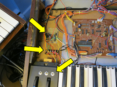
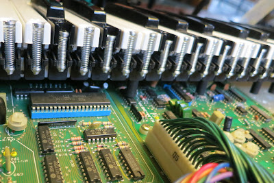
![]() |
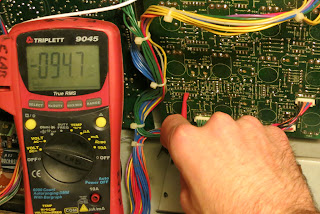
| Probing the Timing of the Key Assigner Circuitry Using my Trusty O-Scope. |
The primary tool for figuring out timing of circuits is an oscilloscope. Or, I could use a Logic Analyzer, which would be better for many of the signals...but I don't have one of those. I do have access to an oscilloscope ("O-scope"), though, so I'll use that.
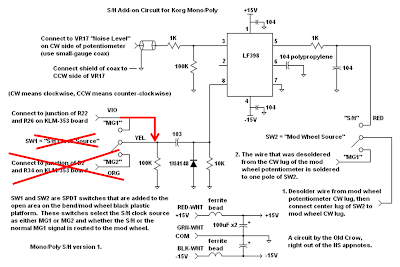
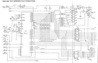
After a quick period of probing around, I found that the Key Assigner has a fundamental timing loop during which is cycles through all six voices. Looking at the schematic, one good place to see this timing loop is at the output of the Pitch CV generator (ie, Pin 1 of IC 9, which is at the top right of the schematic page below).
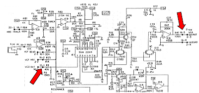
![]() |
| Polysix Schematic for the Key Assigner portion of KLM-366 |
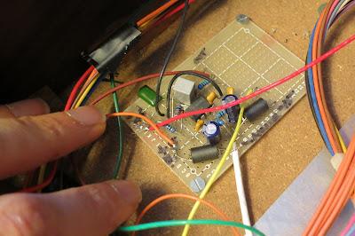
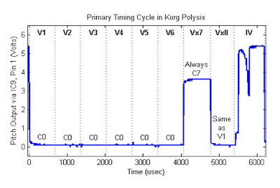
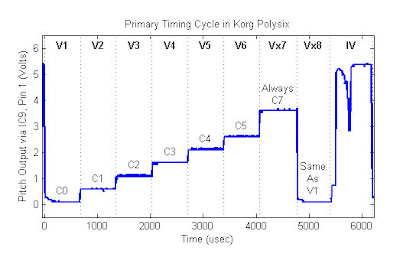
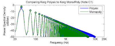
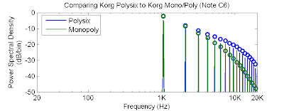
If you put the O-scope probe at this location, you'll see a repeating figure such as the graph below (only one period is shown). The details of the repeating figure depend upon what notes you're playing on the Polysix. The first graph shows the result of playing all "C0" (the lowest note on the keyboard). The second graph shows the result of telling each voice to play a different octave ("C0" through "C5"). By comparing the two graphs, you can definitely see the timing of the six voices.
![]() |
| One Period of the Key Assigner Timing Loop. Output of IC9. All six voices playing "C0". |
![]() |
| Output of IC9 with Each Voice Playing a Different Octave of "C". |
Looking at this graphs, I see that overall timing loop is 6204 microseconds ("usec") long. This means that the basic pitch and the on/off gate of each voice only get updated every 6.2 milliseconds, which is an update rate of only 161 Hz. Frankly, I was surprised at how slow this is. But, since the synth sounds OK, I guess that it works fine. Luckily, the pitch modulations and the VCF and VCA envelopes are not at all dependent upon this loop (they have their own generators which, for the case of the VCF and VCA, are fast).
Additional examination of these graphs (and a little more probing of the synth) allows one to understand the timing cycle well enough to break it into discrete time periods. Clearly, there are six periods associated with the pitch of the six voices. I call these periods
"V1" through
"V6". These periods are each 676 usec in duration.
After V6, there are appears to be another voice-like period, which I call
"Vx7", since it is so much like a voice, but doesn't actually sound. Interestingly, through additional experiements, I found that its voltage is always the same - it is always set to be C7, the highest note on the Polysix. Vx7 is 712 usec long. Why is it a different length than V1-V6? I don't know.
Similarly, after Vx7, there appears to be another voice-like period, which I call
"Vx8". Its voltage level always appears to be identical to V1. I don't know why. I'm thinking that Vx7 and Vx8 are both used by the Polysix's pitch correction circuitry to help it stay in tune. The duration of Vx8 is only 624 usec (though the end of Vx8 is actually a bit hard to define and measure).
After Vx8 is the final period of the Key Assigner's timing cycle. I call it the "Inter-voice" (or
"IV") period. During this period, the synth sets the gate signals, it drives some LEDs, it scans the keybed and some switches, and probably a few other things as well. We'll dig into that in a future post.
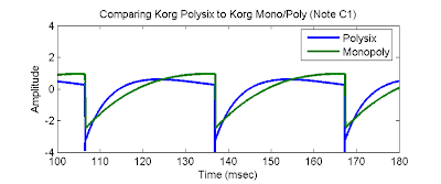
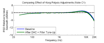
To finish this post, I'd like to show some of the other logic signals that are associated with the timing of the voices. The graph below shows these signals with the same voice boundaries that were derived from the previous graphs.
![]() |
| Logic Signals in the Key Assigner that Appear to be Associated with the Voice Periods |
The INH, A, B, C logic lines are the clock and address lines that the synth uses to keep track of the multiplexed analog pitch signal. As can be seen in the graph, the
INH line goes high at every transition between voices. When high, this signal must inhibit any downstream components from acting upon the pitch signal -- the pitch signal which is about to go through a transition. The INH pulses are about 78 usec in duration. The pulse between Vx7 and Vx8 is a little longer -- about 98 usec. The INH then goes high for the entire IV period, clearly telling the synth to ignore any changes on the multiplexed pitch CV line during the IV period.
During the voice periods, when the INH line goes high, we see that the A, B, and C, address lines toggle their state to indicate that the Key Assigner is switching voices. These three lines act like a binary counter with
A being the low bit (toggles with each voice),
B being the middle bit (toggles every two voices) and, and
C being the high bit (toggles every four voices). Pretty logical. The logical timing even continues during Vx7 and Vx8 as if they were real voices. Once it gets to the IV period, though, the timing of these lines does get a little funky. More investigation will be needed later.
Finally, this graph shows a mystery signal that the schematic names "
MC". I might have thought that this was "Master Clock", but it only seems to change state during Vx7, so it doesn't seem very clock like. I'm not sure what it does. I tried to find where in the multi-page schematic the Polysix uses the MC line, but I couldn't find it. Does anyone have any ideas?
Edit: Here's the Next Step...
Replacing the Key Assigner with an Arduino